Connections
An overview of the extension connectors (see also here) is given in the following image
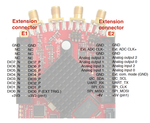
The project uses most but not all connections that are used in the original RedPitaya image. From the connector E2 only the analog inputs and outputs are used. From the connector E1 several pins are reserved for the following purposes:
DIO0_Pfor the ADC and DAC trigger. Connect it with the master'sDIO5_Pto distribute the trigger signal to all RedPitayas in a cluster. As long as the input is high, the DACs and ADCs are running.DIO1_Pis the input for the watchdog (see configuration register section for further details)DIO2_Pis used to acknowledge a received watchdog signal.DIO3_Pcan be set to high, to stop all DACs instantly.DIO4_Poutputs a high for 10 ms after a 100 ms pause on low to provide an alive signal.DIO5_Pcan be set to high via the configuration register to provide the mutual trigger signal.DIO7_P,DIO7_N,DIO6_P,DIO6_N,DIO5_N,DIO4_N,DIO3_N,DIO2_Ncan be used as arbitrary outputs set via the server.DIO2_N(LSB) toDIO4_N(MSB) can output a 3-bit counter configurable bycounterSamplesPerStep!(deactivate with 0)DIO0_NandDIO1_Nare used for the clock selection in a cluster.